Tutorial on Rigging Gears and Chain using a IK Spline Setup..
This is the process I used for my Steampunk Car that I’m currently in the process of creating (will post images up soon)
I used the tutorial from 3D World Issue 154 ~ Create a robot and rig tank tracks as a reference and tweaked the process to use bones and IK Spline Setup.
If there are parts that need more screenshots or clarification let me know.
Maya Rigging – Gears and Chain with IK Spline Setup

- Create part of the chain geometry – duplicate it and then join together to create a chain

- Select all geometry of each section and group them all
- In top view add bone for every connection


- Select Bones and the group node
- Skin > Bind to Skin > Rigid Bind — if move you move one of the bones it should move your chain geometry.
(Edited: For Maya 2015 – Select the Bones and group node and open script editor (windows > General Editor > Script Editor type RigidBindSkin. press Ctrl Enter) - Create curve around gears for chain to follow

- Skeleton > IK Spline handle > options – (use same settings as below)
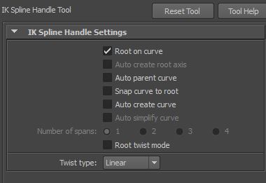
- Select start joint than the end joint and the curve
- The chain should snap around your curve. If your chain doesn’t complete your curve undo the IK Spline and bones and create more geometry and bones. The chain should snap around your curve. If your chain doesn’t complete your curve undo the IK Spline and bones and create more geometry and bones.

- Delete the IK Handle in the Outliner

- This will disconnect the bones from the IK handle but the geometry will still be in place.
- Duplicate the ik curve and name it motion path
- Skeleton > ik spline handle > options (use options below)
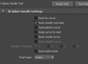
- Select start joint then the end joint and the curve
- It should snap into place again but this time in Outliner you will have a transform group node if you select the node and move it, the chain and bones will follow
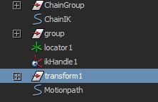
- Using the transfer node we are going to connect it to the motion Path Curve
- Select the transform nod and curve motion path go to Animate > Motion Paths > Attached to Motion Paths Option — I used the options below.

- scrub the timeline and it will move the chain around
- Create two locators name them BigGear and Small Gear
- Select one of the gears and select one of the locators go to
- constrain > point constrain options reset
- The locator should snap into the middle of the gear
- Repeat for the other Gear
- Both locators should be in the middle of the gears

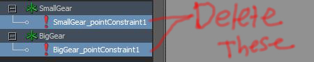
- Go into outliner and delete the Constraint
- Select both locators and freeze transformations
- Select the locator and corresponding gear
- Constrain > Orient – ( you should be able to rotate the gear using the locator)
- Repeat for other Gear
- Create a Nurb Circle — Name is Gear_ctrl
- Select Gear and select circle using the point constraint process as before
- The circle should snap into place centre . Delete the point constraint
- Move, scale and rotate the circle away from the gear slightly so it’s in front and can be selected easily

- Freeze transformations on the circle
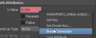
- In the motion path attribute properties break U Value connection
- Select your IK Curve ( the curve that you used for the IK spline
- Isolate it so that you have just the curve visible
- Select all the vertices and go to Create Deformers > Cluster
- Do the same for the Motion Path curve
- Parent Cluster 1 (IK Curve Cluster ) under Cluster 2 (motion Path Cluster)
- Select Motion Path and go to Edit Curve > Reverse Curve Direction ( make sure in Surfaces Menu)
- Open Hypershade ( Windows > Render Editors > Hypershade )
- Select the Motion Path curve in the Outliner
- Click the Input and Output connections button in the Hypershade

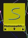
- All the connections of the curve should appear Select the MotionPathShape Node and move it away from the graph

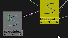
- Create Curve Info node ( located under Utilities ) move it near Curve Shape Node
- Select Curveshape node middle mouse button drag onto curve info node and select other to bring up the connection Editor . Select WordSpace for Outputs and inputCurve for Inputs

- Select the curveinfo node and open the attribute editor .. The arc Length is the length your curve. Make note of the digits

- We are going to create Expression ( This expression is based on 3D world tutorial tweaked code so that it works with this setup ) .,. Change the Length of curve to length of your curve..
(click image to enlarge) - Select the Small Gear Locator and the Big Wheel Locator go to Constrain > Orient
- Select the Gear_ctrl curve and Select Smaller Locator go to Constrain > Orient
- If rotate Gear_ctrl curve the gears and chain should rotate
- If you notice that the gears are flipping or slipping
How I fixed this was in motionPath attribute do below
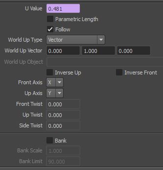
- Rotate the curve a bit so the U value changes.. and unclick follow.
- Now if you rotate the circle it should work fine
- Create Locator named Gears_Moveloc
- Organize the scene like follows
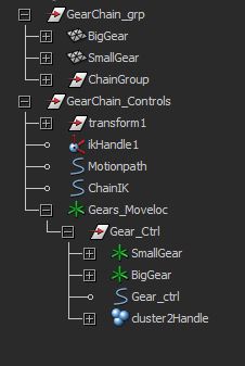
- Select both gear geometry and Ctrl + G to group them.. name group Gears
- Select the Gears_Moveloc locater and the Gear Group node and do Constrain > Parent
- Now you can move the whole rig with Gears_Moveloc


i think you should create a video
Hi,
first of all, great tutorial, helped me a lot, but I’m stuck at step 39. I have no idea what that “Cluster 2 (motion Path Cluster)” is. Do you mean the transform node which comes from the ik spline tool?
If you could clarify that or upload the scene file I would very much appreciate it.
just figured it out 🙂
the solution is to create a cluster from the motion path curve as well before step 39 just like you did it for the IK Curve. then you have the two clusters you need in step 40.
Hi Chris sorry for the late reply, didn’t realize wordpress was not emailing me. I’m glad that the tutorial help you and that you worked it out, thank you for the feedback I’ll update the tutorial. 🙂
I appreciate your tutorial. I had to go through it a few times to really make it work for me. I am rigging up a car engine with a chain drive and this worked perfectly. Thanks
Hey, thanks for the tutorial it worked great 🙂 I was wondering if you knew how to make this rig scalable? Thanks 🙂
Hi, thank you very much for this tutorial. I’ve been trying to rig a motorcycle chain for 3 days, you saved me a lot of time!! Cheers